|
|
|


Design Detention Pond
|
||||||||
|
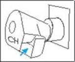
This feature lets you select the design of a Reg-U-Flo ® Vortex
Valve as manufactured by Hydro International. See
www.hydrointernational.biz for details and the locations of
licensees and distributors throughout the world.
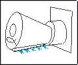
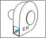
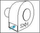
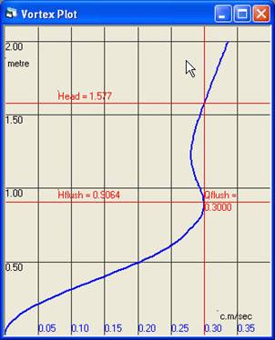
These devices are designed to operate in two modes depending on the driving head. Initially, with low heads the device acts in a similar fashion to an orifice, but as the head increases, the swirl at the entrance creates a vortex that restricts the outflow. The result is that the stage discharge curve is S-shaped and exhibits two turning values. A typical stage-discharge curve is shown below.
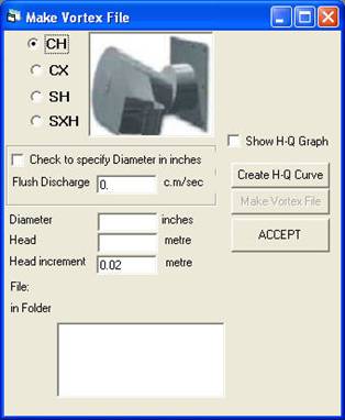
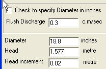
The discharge at the lower turning point is called the Flush Discharge. The reduction of discharge between the two turning points is called the ‘kick-back’. In general, the outlet control should be designed to operate within the stable region between the two head values shown in the plot. In operation with a typical inflow hydrograph the operating point will migrate upwards through the three portions of the S-curve as the inflow increases This is illustrated in Tutorial lesson 25 which describes the response of a simple detention pond to three inflow hydrographs of different peak flow value. MIDUSS comes with a wide variety of pre-defined valves and curve files however it is likely you will need a customized valve and curve to make your detention pond objectives. MIDUSS includes a tool named Make Vortex File which helps you create a file that describes the stage-discharge curve of any of the four types of vortex valves. This file is then used within the detention pond design as a special form of outflow control. Below are example screen shots of the file being generated.
|
||||||||
|
|
||||||||
|
(c) Copyright 1984-2023 Alan A. Smith Inc. |
||||||||
|
|