|
|
|
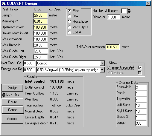
Design Culvert |
|
|
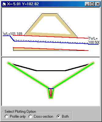
The Culvert command lets you model the behaviour of a culvert under various conditions of flow. Because of the many variables involved, the process is largely one of trial and error and MIDUSS does not suggest initial feasible values for the design. Culvert design can be carried out for either steady, (i.e. time invariant) flow or for an inflow hydrograph. When inflow is in the form of a hydrograph the hydraulic design can be followed by a routing process that shows the attenuation of the inflow hydrograph caused by ponding that occurs upstream of the embankment. In such cases the peak outflow from the barrel will be less than the peak inflow and you can refine the barrel design for the reduced flow if desired. Your Culvert design can be preceded by a Channel design with
either a trapezoidal or
complex cross-section. When this is done the cross-sectional shape
of the channel is ‘inherited’ by
the culvert design and used to describe the flow cross-section
upstream of the culvert. If the
inflow is a flow hydrograph, a channel design may be followed by a
Channel routing process from
which the channel outflow forms the inflow to the culvert.
|
|
|
|
|
|
(c) Copyright 1984-2023 Alan A. Smith Inc. |
|
|
|


